How to Choose Rubber Timing Belts for Your Application?
Choosing the right Rubber Timing Belts begins with the application, not the catalogue. A belt moving a conveyor box needs different priorities than one driving a high-speed packaging spindle. Load, speed, temperature, moisture, chemicals, and available space all matter. Small details matter too. A dusty workshop can change the decision.
Dr. Robert L. Norton, a respected machine-design author, stated, “Design is an iterative process.” That principle fits Rubber Timing Belts well. Engineers may begin with torque and pulley data, then revise the selection after checking tooth engagement, shaft alignment, and installation tension. A belt that looks suitable on paper may still fail beside a hot motor or an incorrectly aligned pulley. I have seen this overlooked. It is not a minor issue.
This guide examines tooth profiles, pitch, belt width, tensile materials, rubber compounds, and operating limits. It also considers noise, maintenance access, expected service life, and replacement availability. For example, a narrow belt may fit the frame but stretch under repeated acceleration. A wider belt may improve load capacity but create clearance problems. Neither choice is automatically better.
Reliable selection requires more than matching a belt to a pulley. Confirm the manufacturer’s technical data. Check the actual duty cycle. Measure the center distance. Question assumptions. Even experienced teams occasionally select for peak load while ignoring start-up shock. That mistake can be expensive.
The goal is practical confidence: a Rubber Timing Belts choice that transfers motion accurately, withstands its environment, and remains serviceable over time. Performance is designed, then verified.
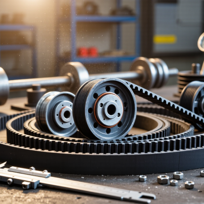
Application Requirements That Define the Right Rubber Timing Belt
How to Choose Rubber Timing Belts for Your Application?
Application requirements define the right rubber timing belt more accurately than a catalog title. Record torque, speed, start-stop frequency, shaft diameter, center distance, and duty cycle. A conveyor carrying heavy cartons needs different reinforcement than a compact printer running continuously. Check shock loads too. They are often underestimated.
The U.S. Department of Energy’s 2023 Motor Systems Market Assessment reports that motor-driven equipment uses about 69% of industrial electricity. That figure makes transmission efficiency and maintenance important design concerns. For high-speed systems, select a pitch and width using rated torque tables, then apply suitable service factors. The IEA’s Energy Efficiency 2023 report states that industry consumes roughly 40% of global final energy. Small transmission losses can become expensive across long operating hours.
Temperature and contamination also shape the choice. Rubber compounds must tolerate heat, oil mist, dust, or occasional moisture. Confirm the cord material and tooth profile, not only the belt width. In field evaluations, poor tension is a frequent failure cause. Too little tension allows tooth jumping; too much tension increases bearing load. Keep alignment precise and inspect pulley wear.
A clean calculation can still mislead. Real machines rarely follow ideal duty cycles. Record actual acceleration and stoppage behavior when possible. I would also challenge an unnecessarily conservative selection: an oversized belt may fit, but it can increase cost, bending resistance, and installation difficulty. Test the chosen belt under the harshest realistic condition before approving production use.
Belt Profiles, Materials, and Construction Options
Choosing a rubber timing belt starts with the belt profile, not the catalogue photo. Trapezoidal teeth suit many general power-transfer systems. Curvilinear profiles usually provide smoother engagement and higher torque capacity. ISO 5296-1 and ISO 5296-2 define key dimensional requirements for timing belts and pulleys. Check tooth pitch, width, and pulley compatibility carefully. A small mismatch can create visible vibration within hours.
Material selection depends on the working environment. Chloroprene rubber performs well in common industrial conditions. HNBR is a stronger option for heat, oil, and demanding duty cycles. Fiberglass cords offer stable length, while aramid cords can improve shock-load resistance. Fabric tooth coverings reduce friction and wear. The Freedonia Group’s Industrial Belts report estimates steady global demand growth through the decade, driven by automation and material-handling equipment. That growth does not make every belt suitable. A dusty conveyor and a high-temperature packaging machine need different constructions.
I normally review startup torque, speed, ambient temperature, chemical exposure, and maintenance access before selecting width. A belt running beside an oily bearing needs more than a wider tooth. It may need better elastomer resistance and improved guarding. In practice, engineers sometimes over-specify tensile strength and overlook pulley alignment. I have seen a technically strong belt fail early because the tension was uneven. Calculate the required tooth engagement, then verify the result through a short operating trial. Real noise, dust, and temperature can challenge a perfect spreadsheet.
How to Choose Rubber Timing Belts for Your Application?
Belt profile, material, and construction should match the required torque, speed, temperature, noise level, and environmental conditions. The chart compares the nominal tooth pitch of commonly used rubber timing belt profiles. Larger-pitch profiles generally support higher torque transmission, while smaller-pitch profiles are often preferred for compact, quieter, and more precise drives.
Neoprene or chloroprene rubber is widely used for general-purpose applications, while polyurethane belts are often selected for higher cleanliness, chemical resistance, and dimensional stability. Fiberglass cords are common for balanced strength and flexibility; steel or aramid cords may be chosen when higher tensile strength, lower stretch, or reduced weight is required.
Calculating Belt Size, Speed, Load, and Torque Needs
Choose a rubber timing belt by calculating, not guessing. ISO 5296 defines timing-belt pitch and tooth geometry, which helps match the belt to the pulley. Start with pulley teeth and pitch. Belt length equals pitch multiplied by tooth count. For example, a 5 mm pitch belt with 120 teeth has a 600 mm pitch length. Measure the center distance, too. Small errors can create tension problems.
Speed and torque come next. Belt speed equals pulley circumference multiplied by rotational speed. A 100 mm pitch-diameter pulley running at 1,800 rpm reaches about 9.4 m/s. Torque equals 9,550 multiplied by power in kilowatts, divided by rpm. A 5 kW motor at 1,500 rpm produces about 31.8 N·m. Add a realistic service factor for starts, shock loads, and temperature. Many engineers use 1.3 to 1.5, but the machine duty should decide. The U.S. Department of Energy’s motor-system guidance identifies alignment and tension as important efficiency controls. Real installations often lose performance there. I have seen clean calculations fail because the frame flexed.
Tips: Check tooth engagement before selecting width. Keep at least six teeth engaged when practical. Verify the belt’s rated capacity against design torque, not nominal torque. Recheck tension after the first operating cycle. Dust, oil, and heat still matter. A wider belt is not always safer; it may hide poor alignment.
Checking Operating Conditions, Maintenance, and Service Life
Choosing a rubber timing belt starts with real operating conditions, not catalog dimensions.
Record speed, torque, start-stop frequency, ambient temperature, and exposure to oil, dust, or water. A belt running beside a hot motor may age faster than one in a clean enclosure. Even small alignment errors can create uneven tooth wear.
Maintenance should be planned around evidence. Inspect tooth profiles, belt edges, cracks, glazing, and unusual dust. Check tension with a suitable gauge, not by thumb pressure alone. The U.S. Department of Energy’s Operations and Maintenance Best Practices Guide reports that predictive maintenance can reduce costs by roughly 8–12% compared with preventive maintenance. That figure is useful, but it is not universal. Poor records can make any savings estimate unreliable.
Service life depends on load, temperature, installation quality, and contamination. Replace a belt before visible failure when downtime is expensive. Keep a simple log: installation date, running hours, tension readings, and inspection photos. ISO 1081 and ISO 5296 provide terminology and dimensional guidance for belt-drive evaluation, but they cannot predict every field failure. A practical mistake is assuming the replacement belt will last like the original. It may not. Recheck the drive after the first operating week, especially if vibration or edge wear appears.

